Jaguar XJR lambda sensor replacement (Upstream bank B)
This page describes diagnosing and changing the upstream bank B lambda sensor in
a 1998 Jaguar XJR, and in a 2001 Jaguar XJR. This sensor fails for a blown heater
coil far more often than the bank A sensor, probably because it is hidden away in
the engine far away from any cooling air flow, and possibly due to Murphy’s law because
it’s much harder to get too!
The page also includes loads of other information about Jaguar lambda sensors that
I’ve picked up along the way and which you may find useful.
Tools
It turned out that this is a job a starter mechanic can do, as long as you have the
right tools for the job. My theory on tools is that having the right one for the
job makes things so much easier and more enjoyable, they are always worth investing
in if they’re not that expensive. For this job I used:
- Large flat-blade screwdriver
- Small mole grips
- Liquid extractor pump (see later)
- Multi-meter
- Sensor removal tool
- Socket set (8mm, 10mm, and 12mm sockets used)
- Irwin bolt grip set
- Right angle screwdriver attachment
- Breaker bar
- Small wire cutters
None of these tools were particularly expensive, all below £20 apart from the socket
set which I already had.

Fault codes
I read the fault codes using an ELM327 wireless DTC reader, and found P1647, which
is the upstream O2 sensor B. I fixed the pipe with superglue and silicone sealant,
and cleared the DTC with the ELM327, but the P1647 code returned.
Diagnosing faults
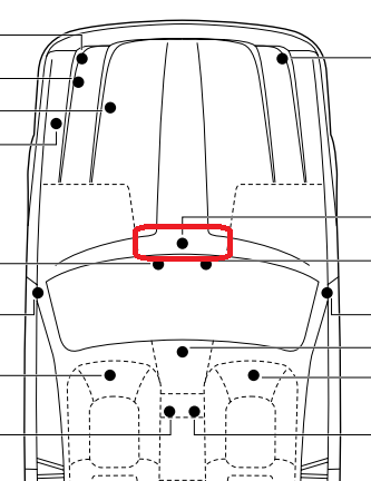
A useful way to tell if it is the senor that is faulty is to switch the A and B banks
over. The DTC for the A bank sensor is P1646. In front of the bulkhead of the car,
you should be able to see the two connectors, one grey (bank B) and one black (bank
A) which are right next to each other.
Swap these over. You will need a long screwdriver to take the connector off its mounting,
and then disconnect them by hand.
Now clear all the DTCs and drive round for a bit, and at least twice turn off the
engine and restart it. If it is the bank B sensor that is faulty, and it usually
is, then you should now get a P1646 code instead. If you still get a P1647, then
it is probably the engine management ECU or the harness between the ECU and the bank
B sensor that is faulty.
Finding the lambda sensor
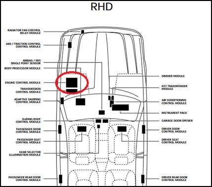
Since the upstream bank B sensor is buried deep in the engine, it is easier to check
the sensor heater coil from the engine management ECU, which is under the cover in
the engine bay on the left hand side of the car near the windscreen:
This is held on with anti-tamper screws, but by pushing down hard enough on them
they are not too hard to remove. I replaced these with normal screws afterwards for
convenience.
Testing for the faulty sensor
The electrical manuals for the 1998 and 2001 XJRs are here:
1998 XJR Electrical System
2001 XJR Electrical System
The most common cause of fault in this sensor is a burned out heater. The wiring
diagram is shown below. This shows that the upstream O2 sensor B heater coil is connected
to the engine management ECU is between pin EM85-02 and a ground which goes to pin
EM85-08 (click on the picture to open it separately).
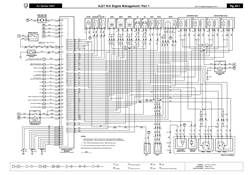
The guide also shows these connectors:

I disconnected connector EM85 and measured the resistance between these two connections
and sure enough it was open circuit.
Buying a new sensor
Now the sensor heater resistance and the sensor’s connector is different between
my 1998 XJR and the 2001 XJR, shown in this table:
|
Car
|
Denso part number
|
Heater resistance
|
Sensor
connector
|
Harness connector
|
|
1998 XJR
|
2344720
|
8W
|

|

|
|
2001 XJR
|
192400-3101
DOX-0428
Jaguar
C2C29250
C2C12588
|
2.5W
|
|
|
For interest, you can have a look at the Denso catalogue for lambda sensors which
explains quite a few things about the sensors. You can find it here.
Here’s the photo of the DOX-0428 from the Denso catalogue:

|
Supplier
|
Part Number
|
|
Jaguar
|
LNE1684BA
C2C12588
C2C29250
22681
C2C7359
C2S2669
|
|
WELLS
|
SU6507
|
|
AutoZone
|
ES10939
|
|
Delphi
|
ES10939
ES10939-11B1
|
|
NGK
|
25631
|
|
AutoZone
|
25631
|
|
Denso
|
192400-3100
192400-3101
192400-3111
DOX-0428
|
|
Interamerican Motor
|
234 9016
|
|
IMC
|
800 26002 039
|
|
WD Express
|
800 26002 039
|
|
Bosch
|
F 00E 262 324
|
|
Beck/Arnley
|
156-6001
|
Many suppliers have supposedly “inter-changeable” parts. The table below shows various
suppliers and their codes that I have found for the 2001 XJR. However, you are taking
a risk if you do not refit exactly the same supplier and type as the faulty sensor
you took off the car. There are variances in heater resistance, signal, and quality
between these. Furthermore, most suppliers will not give a refund if the sensor has
been fitted to a car, but of course you don’t know if the sensor will work until
you have fitted it to the car!
From my experience, and reading other people’s comments on the forums (www.jaguarforums.com
and www.jaguarforum.co.uk) you need to be a bit careful where you get your sensors
from. I purchased one from ebay originally for £24. This turned out to have an open
circuit heater coil too. The guy kindly sent me another one but this one also was
open circuit. In the end he measured all the ones he had which were all open circuit
so kindly gave me a refund. Stories from the forums also recount that most second
hand sensors seem to have the heater coil open circuit too.
The Gendan part was not stamped with “Denso” on it and I think may be a copy part
(although the latest Denso one I have also is not stamped on the part itself). On
their website they only say that it is a “Replacement for Denso part 192400-3101”.
Although it worked fine for a few miles, I then got a “P0174” DTC with the message
“RESTRICTED PERFORMANCE” on the instrument cluster, which I’m guessing is because
the sensor is not giving exactly the right signals. I’ve bought a real Denso sensor
now and will update this page based on the results.
Therefore I would strongly recommend buying an original Denso part, and the first
two rows of the table above are, I believe, Denso parts. Phone and check before buying.
Sensor types
The Denso DOX-0428 is an “A/F” type sensor, which is a little more complex than basic
lambda sensors. Denso’s catalogue has the following information about this:
What is the difference between Zirconia Lambda Sensors and A/F Sensors?
In general A/F Sensors are more sensitive and efficient than conventional Zirconia
Lambda Sensors. This is because of the way each type of Sensor measures the air/fuel
ratio, and the different output signals they produce to indicate the result:
Air/fuel ratio
- A Zirconia Sensor indicates whether the air/fuel ratio is either above or below Lambda
1.00. The engine ECU alters the fuel quantity step by step until the Sensor indicates
that the mixture is wrong again. At this point the ECU starts correcting again, step
by step in the other direction. This method results in a relatively slow and constant
ongoing correction around Lambda 1.00, never able to exactly maintain Lambda 1.00.
- An A/F Sensor indicates the exact air/fuel ratio value. This means that the engine
ECU knows how far off the air/fuel ratio is from Lambda 1.00, and therefore also
knows how much it needs to correct the fuel injection. This allows the engine ECU
to correct the injected fuel quantity to achieve, and maintain Lambda 1.00 almost
immediately.
Output Signal
- A Zirconia Sensor outputs a small voltage between 0V and approx 0,8V, switching from
low to high at around Lambda 1.00 (Fig. 6).
- An A/F Sensor outputs a small current between -10mA and +10mA, where the output is
a stable value, proportional to the air/fuel ratio (Fig. 7).
Overall, especially in changing conditions (sudden accelerations or decelerations)
systems with a Zirconia Sensor will have an under- or overshoot in fuel, resulting
in a less efficient Catalytic Converter.With an A/F Sensor, the engine ECU will notice
fractional changes in air/fuel ratio even in changing conditions. The ECU is therefore
able to make precise adjustments, considerably reducing any under- or overshoot in
fuel. This results in optimal gas conversion inside the Catalytic Converter, resulting
in cleaner air, lower fuel consumption and better drive-ability.

Replacing the sensor
The pictures in this section are from my 1998 XJR. However, the 2001 model is very
similar, differing only in the mounting of the sensor connector, and the three screw
heads that hold the exhaust shield on.
First, I took off the rubber cover in the centre of the engine bay, and the one on
the left hand side of the car, exposing the coolant expansion tank:

First drain the coolant water out of the expansion tank, maybe by using a siphon
tube, an old squirty bleach bottle top (the ones with the trigger), a turkey baster,
or a liquid extractor pump (best):
These are only £14 from www.thisisitstores.co.uk and are very useful. I recommend
it.
Once as much water is removed as possible, next disconnect the plastic water pipes
shown by arrows in the photo. These should be squashed either side with a pair of
pliers (or strong fingers) and pulled off. Be careful with them because the plastic
ring at the end of the connector can easily break. Next undo the two 10mm nuts that
hold the expansion tank in place. These are easy to find.

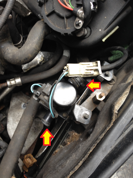
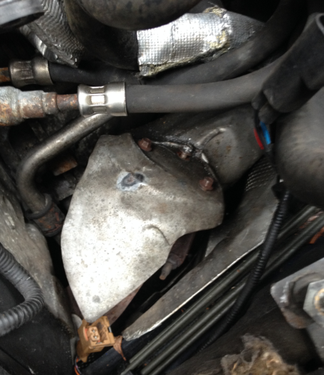
Next you need to remove the object shown in the next photo. I’m not sure what this
is, maybe a valve of some sort, but it has four large rubber hoses going into it,
two each side, and an electrical connector. First remove the hoses. To do this you
will need to use a mole grip to squash the hose clamps together to hold them loose,
then pry off the hose with a screwdriver. A squirt of WD40 first will help the hose
come off. The upper arrow shows one of the hose clips, the lower arrow where the
hose fits onto the object.
It’s worthwhile at this point putting rubber bands on the two upper pipes each side
to make sure they don’t get confused with the lower pipes when you come to re-assemble.
Then undo the three 10mm nuts that hold this thing in place. The nuts are screwed
onto threads on soft rubber mounts which allow the object to move around a little.
The photo above shows the nuts already removed. There are two at the top and one
at the bottom. They are quite easy to access and remove once the hoses are bent out
of the way.
There is another pipe which is best to remove where it joins the side of the car
(which will be nearest where you are working at the side of the car). This is quite
easy to remove and will make the job easier to get it out of the way. It’s likely
that quite a bit of coolant will spill out when you remove this one so be prepared!
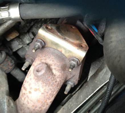
The exhaust heat-shield is now exposed:
This is just a shaped steel plate fixed onto the exhaust downpipe with the three
screws that you can see in the photo. On the 2001 XJR these are Torx screws, but
are hexagonal head (see photo) on the 1998 XJR. A right angle screwdriver attachment
like the one pictured is useful in the restricted space available.

These screws go into the exhaust, and the heat can cause them to seize. For the 1998
car with standard hexagonal head, a set of Irwin bolt grippers does the job on the
rounded screws:

The heat-shield then just lifts off. The plate that held the lambda sensor on is
easy to remove by undoing the two 12mm nuts, although it may not be necessary to,
but you may need all the space you can get to undo the sensor:
The sensor can now finally be seen screwed into the exhaust downpipe:
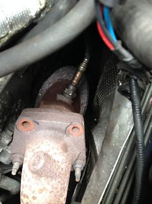
In the photo above it is almost undone. Squirt some more WD40 on it to loosen it
up, then use a sensor removal tool to undo it. A sensor removal tool is essential
for this job:

I bought a set (two) for about £16. I used a breaker bar on the sensor tool. You
can’t turn much angle with the breaker bar, but you only need to get it going.
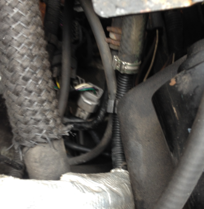
On the 1998 XJR, the sensor’s cable has a cable tie about half way along its length
which is easy enough to cut off with wire cutters, albeit quite a long way down into
the engine bay. On the 2001 XJR the cable goes straight to a mounting plate in front
of the bulkhead.
The other end of the cable terminates in a grey connector. This can be slightly tricky
to disconnect, but not too bad.
Once that grey connector is disconnected the whole sensor can be removed. Note that
the 1998 and 2001 connectors are reversed from each other. The 1998 sensor has a
male connector and the 2001 sensor has a female, so you can’t fit the wrong type
of sensor.
Re-assembly
The new sensor should have a little copper grease wiped around its thread (VERY IMPORTANT:
make sure none gets on the sensing end). Denso sensors supposedly come with a little
tube of copper grease. It should be tightened up to 40-50Nm according to the XJ308
Workshop Manual, or 20Nm according to the Denso fitting sheet – I suggest 20Nm! Use
a torque wrench if possible (if you can get it in there). I couldn’t so just tightened
it hand-tight using the leverage of the sensor removal tube. Make sure the cable
runs along a path well away from the exhaust otherwise it could melt through the
insulation.
When topping up the coolant, you will need to add a little more since you will have
lost a bit when disconnecting the pipes. Fill it up slowly because it takes a while
to trickle down into the empty pipes and will overflow if you go too fast.
Conclusion
Use the DTC reading tool to clear the P1647 code, or do a full reset (disconnect
battery and connect the leads which went to the battery together for a few seconds
– DON’T SHORT OUT THE BATTERY!!!), and it’s done.
All in all I’d say it took me about 4 hours to do the whole job (the first time),
it’s really not that hard even for a very raw mechanic like me.
That leaves buying a new Denso one. The table below summarises my experiences:.
